2.1.
PARTdataManager
2.1.7.
Part view
|  |
| Prev | Next |
As soon as you double-click on a project in the part selection [Part selection] (e.g. part  or assembly
  ), the user interface switches to the parts view [Part view].
In the part view you can specify the characteristic of the part.
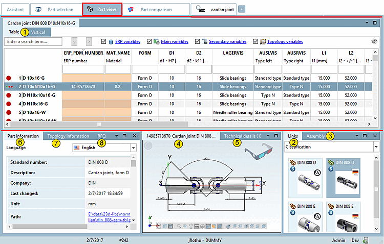
The user interface is organized with docking windows. The following figure shows an overview of these.
Table (the respective standard designation of the loaded part is displayed on the tab)
As sub-areas, you will again see two dockings, which represent two different modes for determining the characteristic.
References [Links] to related objects (see Section 2.1.7.4, “ Docking window "References " ”)
Structure [Assembly] / parts list [Bill of material] (see Section 2.1.7.5, “ Docking window " Structure " ”)
3D preview [Preview 3D] of the object (see Section 2.1.7.6, “Docking window "3D view" ”)
Technical specifications [Technical details] with dimensioned images (see Section 2.1.7.7, “ Docking window " Technical specifications " ”)
Parts information [Part information] (see Section 2.1.7.8, “Docking window "Parts information " ”)
Topology information (see Section 2.1.7.9, “Docking window "Topology information " ”)
Optionally, other dockings are displayed:
2D derivation (see Section 2.1.10, “ Create 2D derivation ”)