5.8.2.1.19.
Output
5.8.2.1.19.4.
Generate image data/preview images in batch run
|  |
| Prev | Next |
![[Note]](images/note.png) | Note |
|---|---|
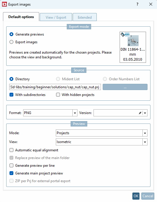
Two basic functions are available via the Generate image data/preview images command:
| |
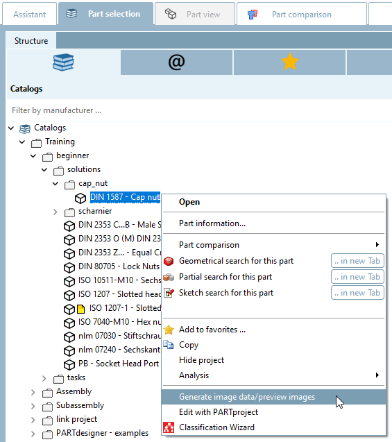
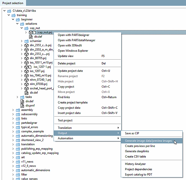
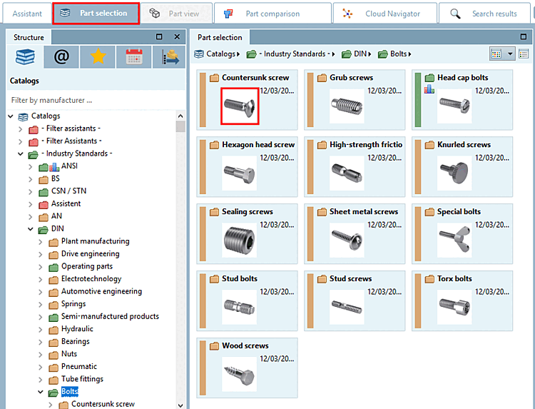
The function is available at project and directory level both in PARTdataManager as well as in PARTproject are available:
To create preview images in the batch run, proceed as follows:
In the following the setting options are explained in detail:
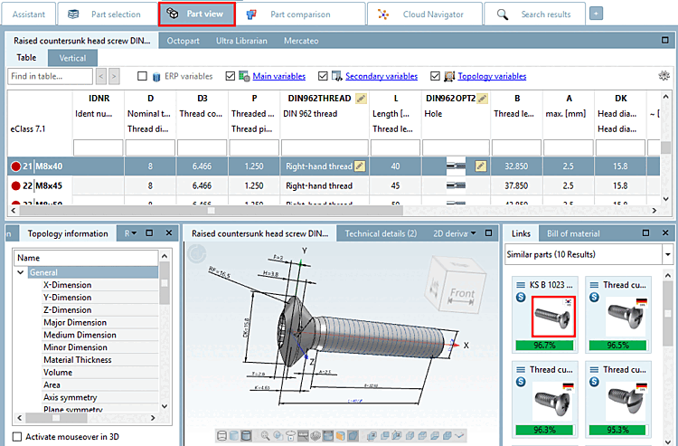
Previews (thumbnails) are displayed in various places.
In the following the complete procedure for preview image creation is explained.
The function is available at project and directory level both in PARTdataManager [21]as well as in PARTproject is available:
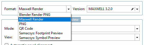
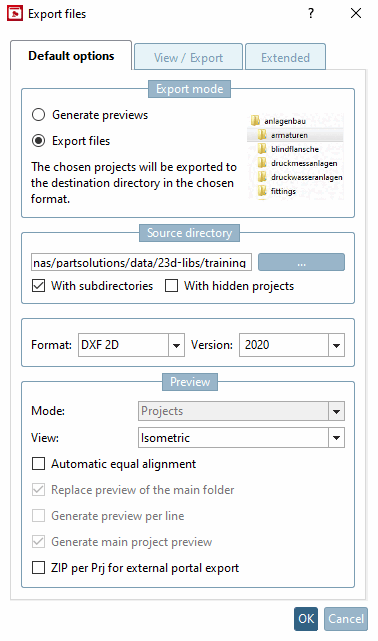
Select the desired format from the list box. All export formats that can generate an image (png) are displayed. The list is generated dynamically and shows what is installed on the system or is permitted by the current license.
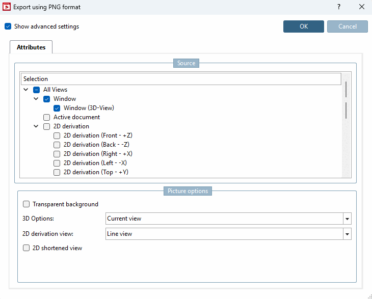
If PNG is selected under Format, the Export in PNG format dialog page opens after confirming the settings with .
The generated preview images have a size of 400 x 400 px.
A detailed description of the settings can be found under Section 2.1.9.3.1, “BMP GIF JPEG PNG TIFF ” in PARTsolutions - User.
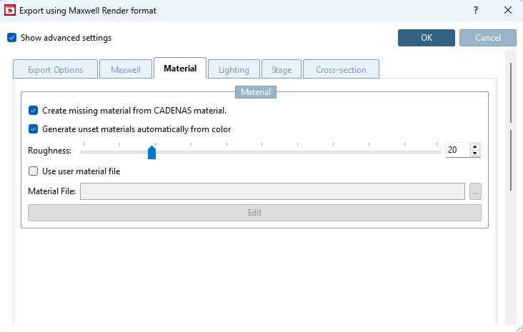
If Maxwell Render is selected under Format, the Export in Maxwell Render format dialog page with many setting options opens after confirming the settings with .
A detailed description of the settings can be found under Section 2.1.9.3.3, “Maxwell Render 3D ” in PARTsolutions - User. If the selection Transfer to server is made under Render [Rendering], the generation is carried out using the PARTrenderManager module, which is also described in this section.
Generate your preview images in the highest quality with POV-Ray Rendering.
If POV-Ray is selected under Format, the Export in POV-Ray format dialog page opens after confirming the settings with .
A detailed description of the settings can be found under Section 2.1.9.3.4, “POV-Ray 3D ” in PARTsolutions - User.
Version: Not required for generating previews [Generate previews]
From the list field, select whether the batch run is to access project or directory level or both.
View: Select the desired perspective for the preview images in the list box.
See also View / Export -> Rotation tab page.
Automatic alignment [Automatic equal alignment]:
All parts are oriented to the X axis with their longest side. If there are two "longest" sides, then one side is randomly selected.
Replace preview of the main folder
The option is only active if either Projects and directories or Directories is selected under Mode.
When all settings have been made, please press .
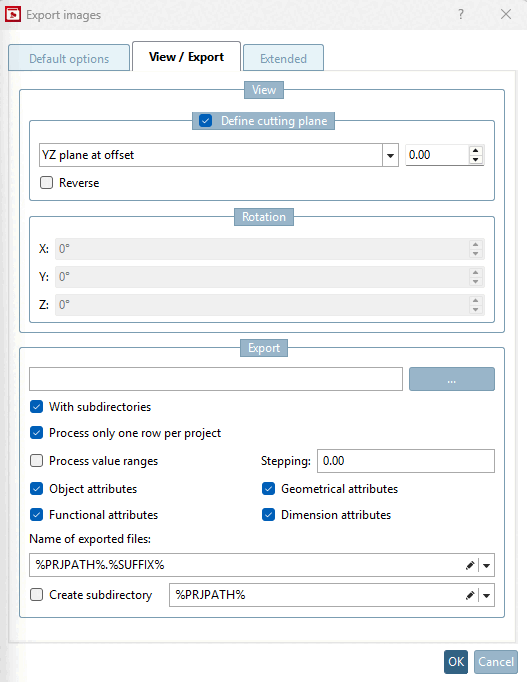
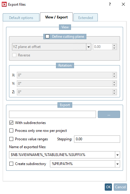
The View dialog area is deactivated by default.
To activate, please place a checkmark in the Define cutting plane checkbox.
In the list field, select the desired sectional plane and offset.
The Rotation dialog area is only active if the Angle input [Angle entry] selection has been made on the Standard options [Default options] tab page under Preview -> View.
The Export dialog area is deactivated when Generate previews is selected.
When all settings have been made, please press .
Storage location of log file for the export procedure.
The default path entered points to your personal user directory. You can use Browse you can change the path.
When all settings have been made, please press .
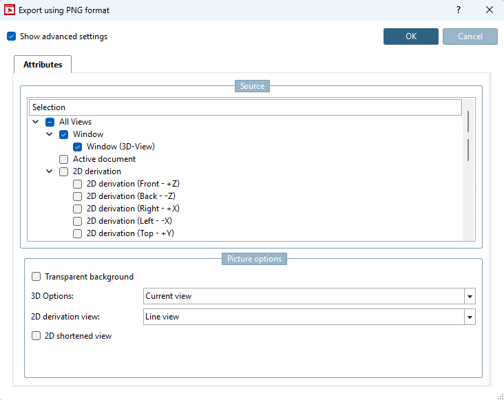
After confirming with in one of the Standard options [Default options], View / Export or Advanced [Extended] dialogs, the Attributes dialog opens.
Image options [Picture options]:
3D settings [3D Options]: The following illustration shows small preview images of the various background settings. You may want to try out which you find most suitable. If the Transparent background option is activated, no background is displayed.
Shortened 2D view [2D shortened view]: See Section 5.10.1, “ 2D derivation: Alternative 2D size (shortened) ”.
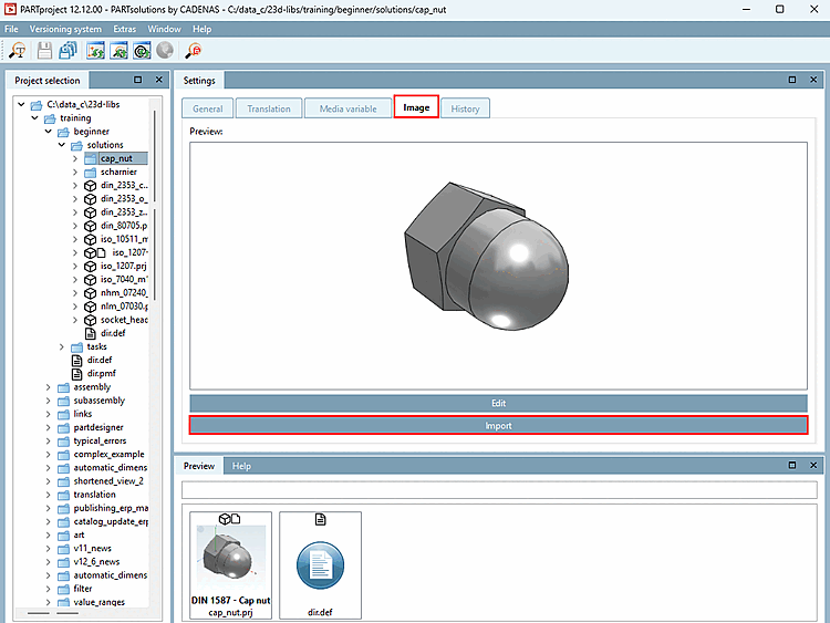
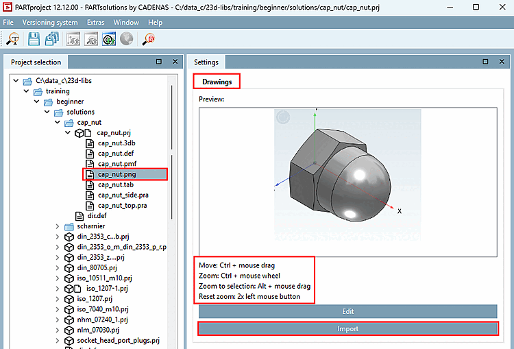
The externally created preview images (*.png) are saved in PARTproject by at directory or project level.
Detailed information can be found on Section 5.9.12, “Tabbed page: Picture ”.
The Export image data [Export images] option is used to export image data in a specific file format to a specified target directory in a batch run. The following file formats are available: Animated GIF, BMP, GIF, JPEG , Maxwell Render, PNG, POV-Ray, QR Code, TIFF.
Depending on the launched CAD all native and neutral formats in addition. (For this, a batch license is required.)
As any errors are logged in a log file, the "exportability" of parts created in ENTERPRISE 3Dfindit can be tested in advance.
In the following the setting options are explained in detail:
Select the desired format in the list field (the format can be specified for certain formats using Version ).
The following file formats are available: Animated GIF, BMP, GIF, JPEG , Maxwell Render, PNG, POV-Ray, QR Code, TIFF. Depending on the CAD started, all native and neutral formats are also available. Compare the formats that can be selected in the PARTdataManager export [Export] menu. Detailed information on the export formats can be found under Section 2.1.9, “ Export to various file formats (without 3Dfindit interface) ” in PARTsolutions - User.
This setting remains inactive in the "Export files [Export files] " export mode [Export mode].
View: Select the desired perspective for the preview images in the list box.
See also Rotation.
Specify a target directory for the export files using Browse . to specify a target directory for the export files.
You can include subdirectories for the generation of the export files optionally.
Process [Process only one row per project] only one line per project:
Limit the read table lines to one characteristic per project file.
Project files with value ranges can be split by specifying an increment [Stepping width]. If this option is deactivated, only the currently set value (i.e. a characteristic) is read out.
Select the desired option for the naming rule in the list box.
The file name of the export file is composed according to the defined syntax. You can find some examples in the list field:
E.g. standard designation NB, followed by view name VIEWNAME (e.g. front view) and the file extension SUFFIX . You can of course change this composition to suit your requirements.
When all settings have been made, please press .
[21] Only in developer mode. Detailed information on setting the mode can be found under Section 1.7.3.3.3.1, “ Key "IsAdmin" - User mode ” in ENTERPRISE 3Dfindit (Professional) - Administration.
![Error when creating the index. Make sure that an index has been created for the base element. [Error on index creation. Make sure that an index was created for the baseitem.]](resources/img/img_2ebe271b562d4446b9b43f90368c7baa.png)
![[Warning]](images/warning.png)
![Export mode: Generate previews -> "Advanced [Extended] " tab page](resources/img/img_5148ee90c1174235a5f7b6c7bd94d4be.png)
![Line display [Line view]](resources/img/img_9b44a2e29c814d07849a3cb33f7e3525.png)
![Lines + shaded display [Lines + shaded view]](resources/img/img_dd6884cb3ea1446d949b9ee50cf14bc6.png)
![Shaded display [Shaded view]](resources/img/img_f634fbebadaf421da1612c9009b7c0ae.png)
![Export mode: Export files -> "Advanced [Extended] " tab page](resources/img/img_e252173aa5224fc0b91355e63b653368.png)