7.13.5.1.2.
Properties...
7.13.5.1.2.3.
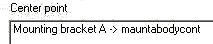
Center point
|  |
| Prev | Next |
![[Note]](images/note.png) | Note |
|---|---|
As of V11 only displayed at old assemblies which already used this feature. Do not use for new creation. | |
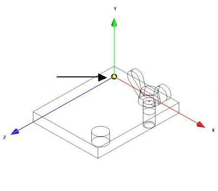
In the right-hand half of the window, you can define the position of the assembly within the 3D preview [Preview 3D] or in the CAD system. This function is intended for realigning the entire assembly.
If you want to position the assembly individually in the coordinate system starting from an attachment point, click on the button.
-> The Select connection [Choose connection point] point window window opens.
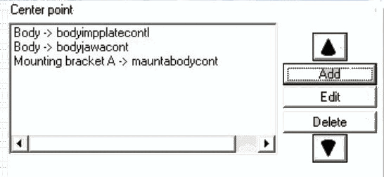
"Select connection point [Choose connection point] " dialog (in this example, "Base plate" and "Hole 1" are selected)
Select a connection part [Connection part] and a connection point [Connection point]. This defines a starting point for the "repositioning".
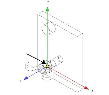
The assembly is no longer aligned according to the presetting (corner of the plate in the zero point of the KO system), but according to the connection point hole 1 (see illustration).
Further explanations on Select connection [Choose connection point] point:
Further explanations on the properties of the assembly [Assembly properties]:
You can also link the positions that you define in the Zero point [Center point] field and the X, Y and Z fields using AND or OR.
AND - When combining the position specifications via AND, both specifications are taken into account, i.e. added together.
OR - With the combination via OR, for example, the setting in the zero point [Center point] field (butterfly screw 1 -> S 1) only applies if the assembly component butterfly screw 1 is already part of the current assembly.
!["Select connection point [Choose connection point] " dialog (in this example, "Base plate" and "Hole 1" are selected)](resources/img/img_141afe76067440e18f9e1dda30f7ad3f.png)
![Select connection point [Choose connection point] " dialog](resources/img/img_3a1558628225425fa6f4ee6e91c641de.png)