7.10.1.
Create 2D derivation
7.10.1.2.
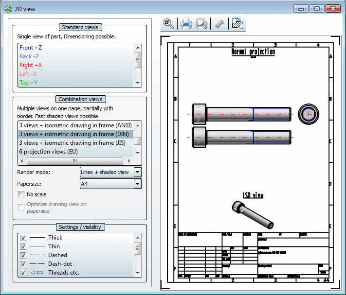
2D view" dialog box
|  |
| Prev | Next |
The selection and settings within the 2D view dialog window form the basis for displaying the object in your CAD system.
As soon as you click on a view, the 2D derivation of the part is created.
![[Note]](images/note.png) | Note |
|---|---|
The shaded display [Shaded view] option is an exception to the combination views [Combination views]. Here, the 2D derivation is only created if it is transferred to the CAD system. See Section 7.10.1.2.2, “ Combination views ”. | |
When all settings have been made, click  Transfer to CAD.
The settings area of the dialog page is subdivided as follows:
The individual areas are explained in the following sections.