1.3.5.2. Tabbed page "Elements"
1.3.5.2.1.
Representation
|  |
| Prev | Next |
You can make the following settings in the Display dialog area:
Shading: Set how the shading should be displayed in the 3D view.
In the drop-down menu, you can choose between the options Edges, Hidden edges (gray) [Hidden lines (gray)], Hidden edges [Hidden lines], Shaded, Shaded with edges and Schematic.
![[Note]](images/note.png) | Note |
|---|---|
The setting only refers to the default setting when loading the component. You can change the display mode using the corresponding toolbars in the program interface. | |
Representation of the component in plastic 3D preview. The three-dimensional effect only occurs when using red-cyan glasses!
The selected part is displayed in alignment to enhance the three-dimensional effect. The background is automatically darkened. The red/cyan effect option can be used regardless of the display mode (Lines [Lines], Hidden edges [Hidden lines], Shaded, etc.).
|
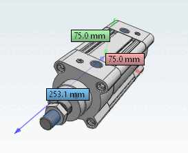
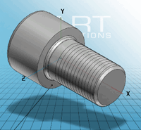
Coordinate system Show dimensions [Show coordinate system dimensions]
Use the checkbox to switch the display of dimensions on or off. |
|
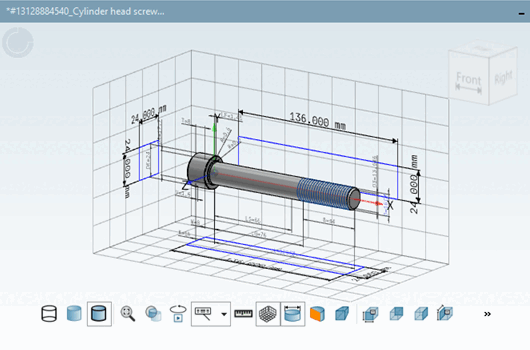
Display measuring grid [Show measuring grid]
If this checkbox is activated, the dimension grid remains active even after restarting the software. The toolbar button in the 3D viewer works independently of this checkbox and does not remain active after a restart.
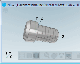
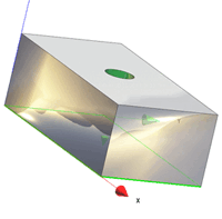
Coordinate system (small): Select whether and, if so, in which corner of the 3D view the coordinate system should be displayed for orientation.
Coordinate system type (small) [Type of coordinate system (small)]: Specify whether you want to use the orientation cube [Orientation cube] or the coordinate system for easier navigation.
Perspective display [Perspective view]: Switch the perspective view.
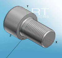
View after loading: Specify the view with which you want the component to be displayed after initial loading.
Gloss texture [Highlight texture]
Connection points (PartDatamanager) and connection points (PartDesigner) [Connection points (PartDesigner)]: Determines separately whether connection points [Connection points] are to be displayed in the PARTdataManager or in the PARTdesigner. You can adjust the view at any time using the Show connection points menu.
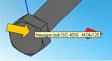
Tooltips for components [Tooltips for parts]
See also Section 5.12.5, “Classify connection points ” in eCATALOG 3Dfindit.
Align labels to coordinate axes: Aligns the texts to the coordinate system.
!["Texts and classes [Texts and classes]" deactivated](resources/img/img_aa61f17e188d43d4beed5940b7072219.png)
!["Texts and classes [Texts and classes]" activated](resources/img/img_c441198253214e3dbf480cd236d4c470.png)