7.9.3.4.1. Connection points
for assembly construction
7.9.3.4.1.1. Connection points in general
|  |
| Prev | Next |
7.9.3.4.1. Connection points
for assembly construction
7.9.3.4.1.1. Connection points in general
| |
| Prev | Next |
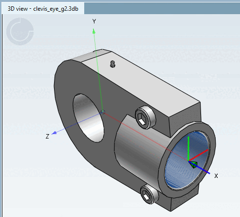
The parts created in the PARTdesigner can be configured [Configurator] with the configurator[101] to assemblies. To do this, the parts must already have PARTdesigner precisely defined and named connection and insertion points must be assigned to the parts.
A cuboid contains a boring into which a screw is to be inserted later (assembly configuration). Therefore a connection point needs to be applied for the boring.
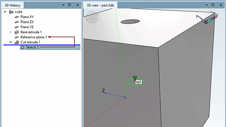
Click on the area [Face] in which the hole is located. --> The corresponding sketch [Sketch] appears in the history [History] with a colored background.
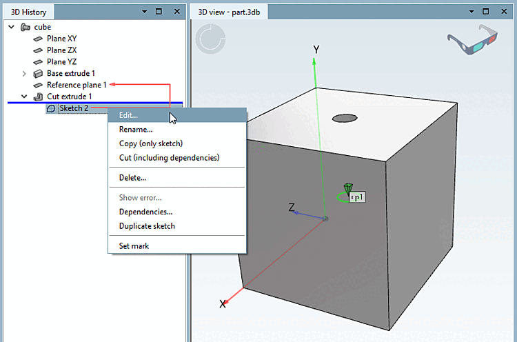
Right-click on the context menu of the sketch (in this example, Sketch 2).
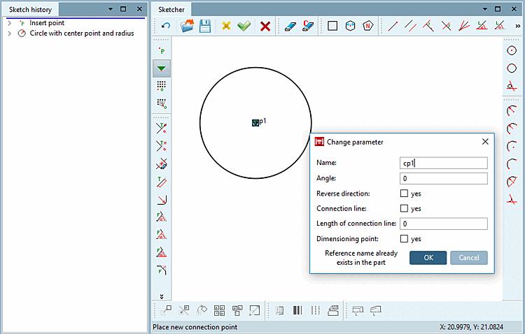
"Catch" the center of the circle (boring) with your cursor and affix it with a simple mouse-click.
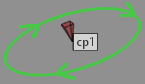
--> The point gets a green triangle symbol .
--> The Change parameters [Change parameter] window opens.
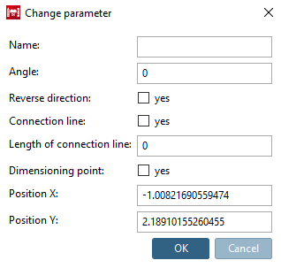
If you place the connection point freely (without "snap"), the options Position X and Position Y are also available in the dialog.
Specify a name for the connection point - e.g. cp1 - and confirm with .
Optionally, you may make changes in the other fields as well.
Angle: Rotation of the connection point
| ||||
You can find another use case at Section 7.9.3.4.1.4, “ Connection points on miters ”.
Reverse direction [Reverse direction]: Reversing the direction is required for a hinge, for example. The hinges should fit together in opposite directions.
Insertion line [Connection line] and length of the insertion line [Length of connection line]: Insertion lines can be used for movable elements. For example, for connectors of profiles that move in a groove. See Section 5.18.1.4, “ Create insertion line ”.
Dimension point [Dimensioning point]: Activate this option if a connection point should also be used as a dimension point. See Section 7.16, “ Docking window "Dimensions " ”.
Click on the
button Accept changes
 .
.
--> The sketcher [Sketcher] is closed.
--> In the 3D view, the connection point is also indicated by a three-dimensional green triangle symbol .
By default, the coordinate system is not shown at connection points.
However, you can it enable by setting the key value to "1" (under $CADENAS_USER).
[Settings3DPane]
cpCoordinateSystem=1

![[Note]](images/note.png)