7.6.2.6.
Base extrude / Base rotate
7.6.2.6.1.
Extrude...
|  |
| Prev | Next |
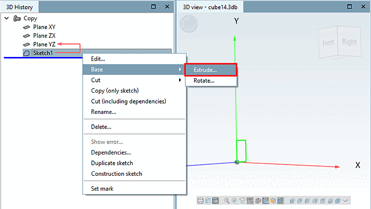
Call: Solids [Base] > Extrude...
→ The sketch is displayed in the 3D view
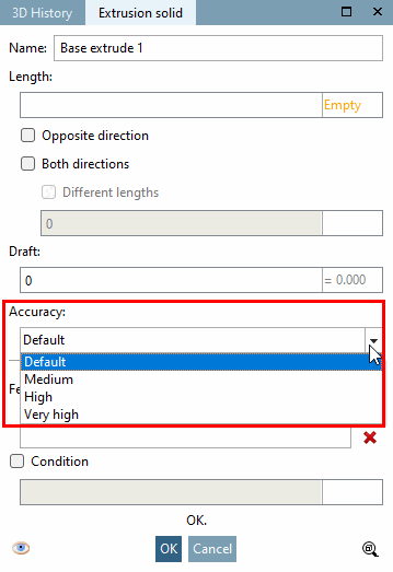
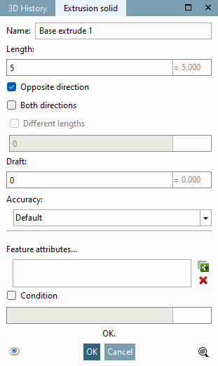
→ The Extrude... command opens the Extrusion object [Extrusion solid] dialog box.
As soon as complete entries have been made, a preview appears in the 3D view and changes are displayed immediately.
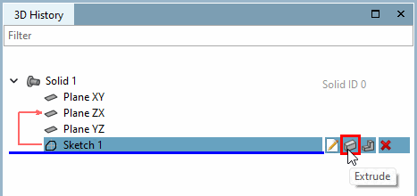
Name: "Base extrude <number>" appears by default. The number is incremented with each extrusion.
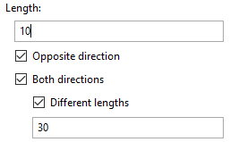
In the Length field, you define the extent of the 2D object.
|
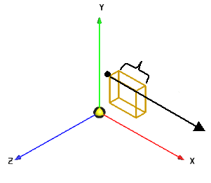
Opposite direction extrusion is carried out in the opposite direction. |
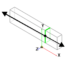
Both directions: The extrusion is performed in both directions. |
|
|
|
|
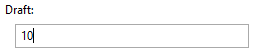
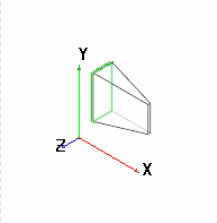
Shaped be [Draft] velto create a bevel from the 2D sketch, enter the corresponding angle dimension in the Shape bevel field. |
|
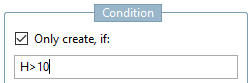
You can also link each extrusion to a condition [Condition] condition. Possible characters are &, |, !=, =, >, <, >= and <=. |
|
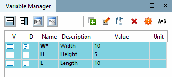
Example: The sketch should only be extruded if for variable H (height) a value larger than 10 has been set. |
Design steps (features) that are excluded due to the condition are shown deactivated in the 3D history [3D History] and marked with an if symbol ( for Base
  for Cut).
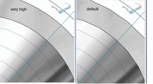
Minimal rasterization [Minimum rasterization]:
In some rare situations, it may be necessary to increase the accuracy for the minimum rasterization within a part for a specific feature in order to be able to create a specific geometry. You will find this setting option under Solids [Base], Cut and Sweep.
![[Note]](images/note.png)
![Black vector = direction: against surface normal [Against surface normal]](resources/img/img_c80a61e4e1b547daa4bc85f4fe36ac0a.png)
![Black vector = direction: both directions [Both directions]](resources/img/img_d36353949f96466080a7c84a99627525.png)