3.6.3. Simulation -
Specification for Mechatronics Concept Designer (MCD) 3.6.3.3. Limits of
joints (MCD) |  |
| Prev | Next |
3.6.3. Simulation -
Specification for Mechatronics Concept Designer (MCD) 3.6.3.3. Limits of
joints (MCD) | |
| Prev | Next |
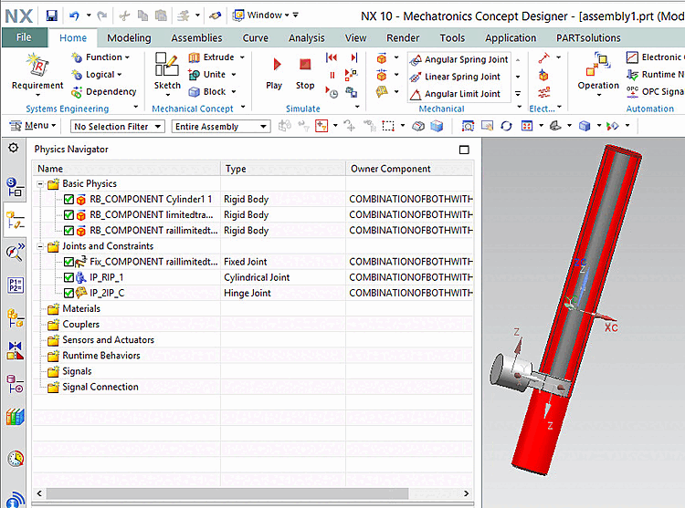
Rigid bodies and joints are created at the assembly level from solid body instances in assembly components and assembly constraints respectively.
The corresponding functionality can be found on the Physics Navigator tab.
Above you can find the Rigid Bodies, below the joints. When clicking on a joint, then above the two connected components are marked with red.
The Rigid Bodies' name is the Journal Identifier of its Component source.
There are 3 types of connections and constraints:
Fixed connection: Created from fixed mates
If the component is unconstrained, then fix joints are created. These joints immobilize the "Attachment" component, just like the "Fix" constraints do.
Hinge joint: Created from rotate mates
Freedom of movement along just the RotateZ mate results in Hinge Joints
Cylindrical joint: Created from rotate and translate mates
Freedom of movement along the TranslateZ and (optionally) RotateZ mate results in Cylindrical Joints.
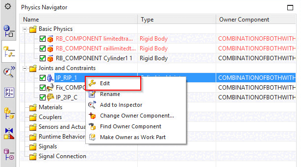
For hinge and cylindrical joints, you can specify joint limits that define an acceptable range of motion for the joint.
In the context menu under Connections and constraints, you will find the Edit context menu command.
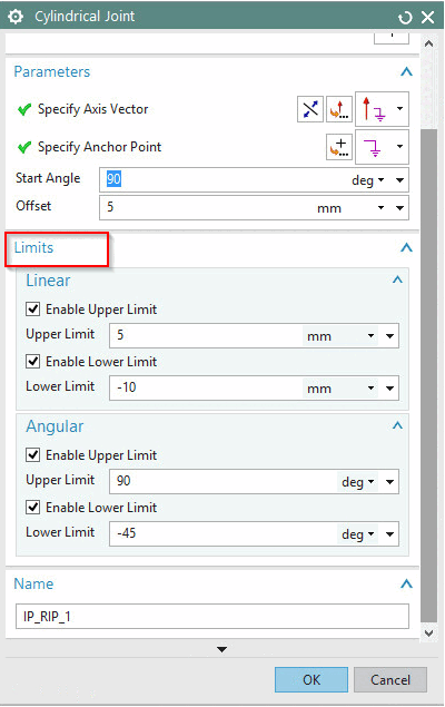
-> The corresponding dialog box appears with a Limits dialog area.
Linear limits are based on translate mates. Angular limits are based on rotate mates.[9] [10]
Connections are stored on layer 33 by default.
layer_12=joints:33:4
Key and key value have the following structure:
Layer_IND=element_name : layer_number:layer_status : category
If the port name (port name variable) is provided in ifugnx.cfg, then this is also used for the corresponding connection, otherwise the name is created from the connection point names of the two connection parts.
In order to have the functionality available in the Mechatronics Concept Designer, the key EnableMCDmust be set to 1 (default is 0) under $CADENAS_SETUP/ifugnx.cfg.
Furthermore the respective NX license "mcd_core" has to be accessible.
![[Note]](images/note.png)