3.5. Modeling
guideline for BIM 3.5.3. Regular Bodies
for VDI Models |  |
| Prev | Next |
Modeling for the VDI field should ideally be performed with simple regular bodies[7], in order to ensure a correct export into the VDI format.
The following describes, with the help of examples, how bodies should be designed, meaning the number of features, feature types, etc.
In general terms: Bodies should be modeled as simple as possible.
Please note: VDI export ONLY supports feature colors, NOT surface colors $CADENAS_USER the configuration file debug.cfg must contain the block [PDESIGNER] with the key allowFeatureAttribueAll=1. If no debug.cfg exists yet, create the file.
The following features should never appear in :
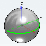
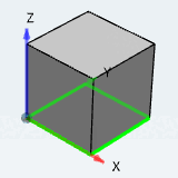
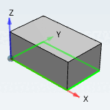
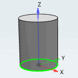
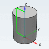
The simplest solids are the sphere, cylinder and box. Modeling with these control solids results in an optimal output for VDI. These control bodies do not contain any "TRANS" or "ROTA" in the VDI code
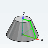
If something cannot be modeled with regular bodies, you can also use bodies which have "ROTA" (rotation) in their VDI code.
No occurrence of "TRAN" or "ROTA".
960;2;1;1Y;1_cube;bmp;Vorschau; 970;1;Cube 100 7;;QUAD;0;-50;-100;1;0;0;0;1;0;100;100;100; 970.02;1;G;QUAD;100;-50;0;-1;0;0;0;1;0;100;100;100;;;;;;;;1; 970.04;1;0.689999997615814;0.689999997615814;0.689999997615814;1;0.34499999880791; 0.34499999880791;0.34499999880791;1;1;1;1;1;20;0.0053906249813735;0.0053906249813735;0.0053906249813735;1;
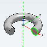
970;1;Torus 100-25 7;;QUAD;-12.5;-62.5000000000004;-12.5000000000002;1;0;0;0;1;0;125;
In the following listing, different bodies are subdivided in the categories 1 to 4. Bodies from the categories 1 to 3 may be used. All not mentioned there fall under category 4 and may NOT be used.
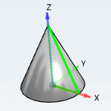
"Cone Rotated" based on a rotated triangle
(does not belong to the 1st order control bodies, but also has no "TRANS" or "ROTA" in the VDI code)
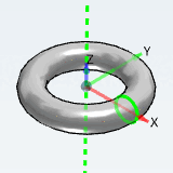
Once a bevelled rectangle is rotated, "ROTA" occurs in VDI code. A rotated circle also results in "ROTA" in code (Torus and Torus sector).
All bodies not mentioned above fall under category 4. They may not be used for VDI-compliant modeling and they do not comply to LOG200/300.
When modelling for the BIM sector the following applies in addition:
[7] "Regular solids" are solids that were created on the basis of very simple sketches such as semicircles, rectangles or circles. A